Mechanical Equilibrium
Newton’s Laws
Let’s review Newton’s Laws that we introduced from last time:
- If the net force on an object is zero, the object will remain at constant velocity. This means things that are at rest, stay at rest, and things that are moving continue to move at constant velocity.
- The sum of all the forces on an object, $\sum \vec{F}$, is called the net force $\vec{F}_{\text{net}}$, and is given by \(\sum \vec{F}=\vec{F}_{\text{net}}=m\vec{a}\).
- For two objects $1$ and $2$ in contact, \(\vec{F}_{1\rightarrow 2}=-\vec{F}_{2\rightarrow 1}\).
Today, we’ll be talking about systems in mechanical equilibrium and how this relates to these set of laws.
Mechanical Equilibrium
Put simply, a system is in mechanical equilibrium if $\sum \vec{F}=0$. By definition, nothing is moving since there is no net force on objects in mechanical equilibrium (or everything is moving at constant velocity, but this situation is much less likely). We’ll talk about some of the common problems involving mechanical equilibrium here.
Hanging Masses
Hanging mass problems are simply trigonometry problems in disguise. A common setup might look something like this:
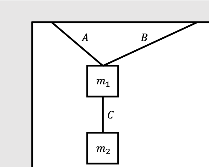
What’s happening here? Ropes $A$ and $B$ are holding the weight of two objects of masses $m_1$ and $m_2$ from the ceiling. Rope $C$ holds $m_1$ and $m_2$ together. Because of gravity pulling on the blocks, the ropes have tension that are pulling on them, which are therefore also pulling on the blocks in order to prevent them from falling from the ceiling. Usually for these problems, we assume that the ropes are massless. A common problem might ask you to solve for the mass of one of the objects given that you know the tension force acting on the objects, or vice versa. To study this system more carefully, we construct a force diagram for the objects of interest. Force diagrams (sometimes called free body diagrams) are simply diagrams that illustrate all the different forces acting on an object. Let’s consider the force diagrams for both masses $m_1$ and $m_2$:
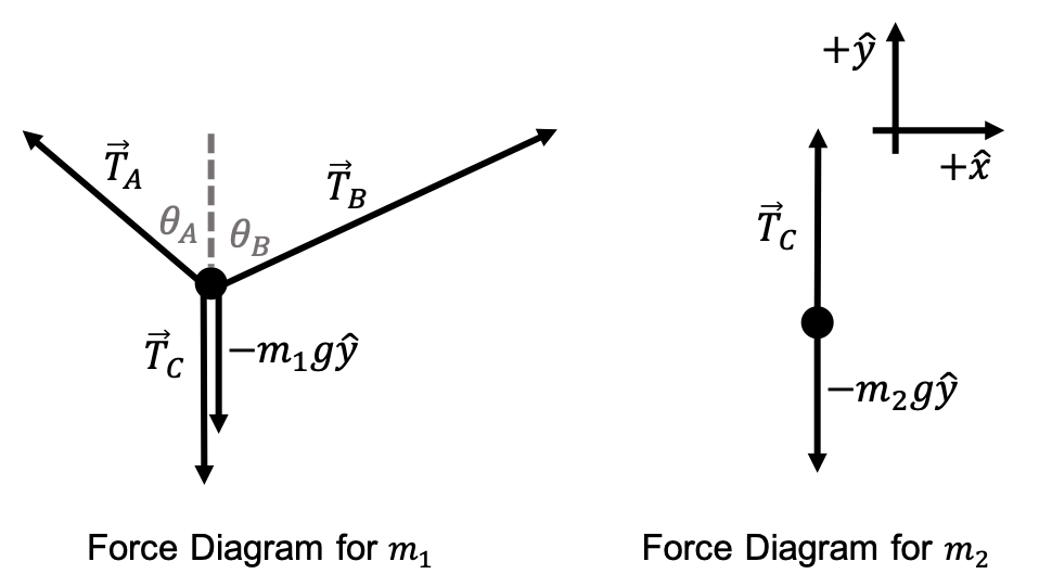
We’re denoting $\vec{T}_A$ as the force of tension from rope $A$, and the same for $\vec{T}_B$ and $\vec{T}_C$. $\vec{T}_A$ and $\vec{T}_B$ are holding the mass $m_1$ up, while $\vec{T}_C$ is pulling the mass $m_1$ down. However, $\vec{T}_C$ is pulling $m_2$ up. Obviously, we also have the forces of gravity acting on each of the objects, which we know to have magnitude $mg$ and always point in the downwards direction. We also took the liberty of defining the angles $\theta_A, \theta_B$. Together, these forces comprise all of the forces in our system.
Because none of the masses are moving, we know that our system is in mechanical equilibrium. This means for both of the blocks individually, $\sum \vec{F}=0$:
\[\vec{T}_A+\vec{T}_B-\vec{T}_C-m_1g\hat{y}=0, \quad \vec{T}_C-m_2g\hat{y}=0\]Of course, these equations aren’t really useful to useful to us in vector notation. We have to break them down to their $\hat{x}$ and $\hat{y}$ components. This gives us four equations:
- $+\hat{x}$ component for $m_1$: $\quad -T_A\sin\theta_A+T_B\sin\theta_B=0$
- $+\hat{y}$ component for $m_1$: $\quad T_A\cos\theta_A+T_B\cos\theta_B-T_C-m_1g=0$
- $+\hat{x}$ component for $m_2$: $\quad 0=0$
- $+\hat{y}$ component for $m_2$: $\quad T_C-m_2g=0$
We can solve these equations for any combination of $T_A, T_B, T_C, \theta_A, \theta_B, m_1, m_2$ according to the exact specifications of what a given question is asking. This illustrates the general pipeline of how to approach these problems:
- Draw a diagram of the setup.
- Account for all of the forces on the different objects in their respective force diagrams.
- Use Newton’s second law of $\sum \vec{F}=0$ for each of the individual objects in mechanical equilibrium.
- Solve for the relevant quantities.
Sliding Masses
Masses on a ramp are another common type of classical physics problem. The idea is you have some block (or blocks) that’s resting on an inclined plane, and we want to study the system’s properties. For example, at what angle of the inclined plane will the block begin to slide off the ramp? A diagram of the setup might look something like this:
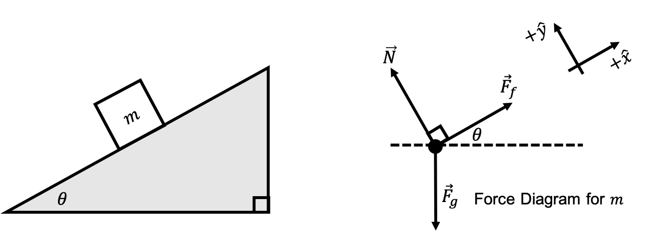
While this ostensibly looks like a simple problem, it introduces a lot of new concepts that are worth talking about. We took the liberty of also setting up the force diagram for the single mass $m$ of the system. There are a number of things that are different about this system compared to the previous example:
- Take a look at the $\hat{x}$ and $\hat{y}$ axis: they’re slanted! For sliding mass problems, it’s usually most convenience to rotate our coordinate system to align with the ramp. Of course, you could do all of our calculations in our standard $xy$ axis system, but it’s a lot hairier. The laws of physics must hold in any static reference frame, so we can always take the liberty of choosing an axis system that’s most convenient for us.
- Because we have a slanted coordinate system, gravity is no longer pointing in the $-\hat{y}$ direction! You have to use trigonometry to figure out the direction of gravity in this slanted reference frame.
- We have a new type of force that we’re working with now: the normal force. Normal force is the force exerted by one object (i.e. the ramp) in contact with the other (i.e. the block) in order to support the object under gravity. Other examples might include how the chair you’re sitting on or the floor underneath you are exerting a normal force on you to prevent you from falling to the center of the Earth. Usually, we denote the normal force on an object as $\vec{N}$. Normal forces are always perpendicular to the surface. We can determine the magnitude of the normal force through Newton’s second law, as we’ll see later.
- There’s another new type of force as well: friction. Friction is simply a force that opposes the motion of objects. The object isn’t sliding down the ramp yet because static friction is keeping it from sliding. Static friction is always equal to just enough force to keep the object from starting to move, and always acts in the direction opposite from the (desired) motion of the object. Of course, if static friction can’t provide enough force to stop the block from moving, then the mass will start sliding down the ramp. We will see how to find this transition point later. There is also kinetic friction, which is essentially the same idea but is in effect when the object is moving. We’ll talk about kinetic friction later.
Once again, we have a system that’s in mechanical equilibrium since nothing is moving. So, all we have to do is balance the forces in the $\hat{x}$ and $\hat{y}$ directions separately.
\[F_f-F_{g, x}=F_f-mg\sin\theta=0, \quad N-F_{g, y}=N-mg\cos\theta=0\]Solving this system of equations gives us
\[\vec{F}_f=mg\sin\theta\hat{x}, \quad \vec{N}=mg\cos\theta\hat{y}\]This effectively describes our system as long as the static friction $\vec{F}_f$ is less than the “transition point” maximum friction magnitude (meaning we want $\theta$ to be small).
Exercises
Problem 1
Consider a single mass $m$ hanging by two massless ropes $A$ and $B$.
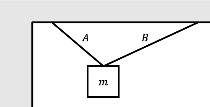
We know that the angle made by rope $A$ from the vertical $\theta_A=\pi/4$, and the angle made by rope $B$ from the vertical $\theta_B=\pi/3$.
- Draw the force diagram for mass $m$. You should have three different forces that are all accounted for.
- Write the mechanical equilibrium force condition in the $\hat{x}$ direction.
- Write the mechanical equilibrium force condition in the $\hat{y}$ direction.
- Solve for the magnitude of the tension in both ropes $A$ and $B$ as a function of $m$.
- The maximum tension that both of the ropes can individually handle before breaking is $1000\text{ N}$. How massive of an object $m$ can be held before one (or both) of the ropes break? Assume $g=10\text{ m}\cdot\text{ sec}^{-2}$ if necessary.
Problem 2
Consider a very strong man trying to push a block up a frictionless incline plane.
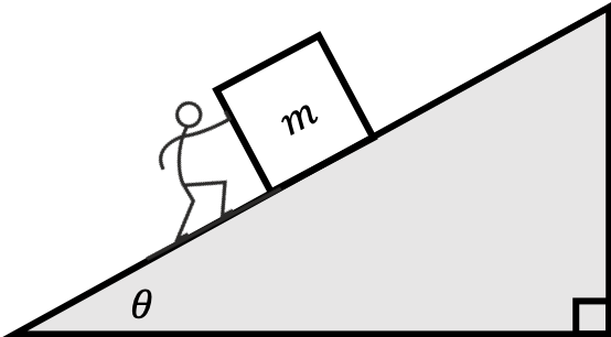
Answer the following questions:
- Draw the force diagram for mass $m$. You should have three different forces that are all accounted for. Take care in choosing your coordinate system.
- Write the mechanical equilibrium force condition in the $\hat{x}$ direction.
- Write the mechanical equilibrium force condition in the $\hat{y}$ direction.
- Solve for the normal force and force from the man required to keep the block not moving.
- The man is very strong and can push with a maximum force of $200\text{ N}$. Assuming that $g=10\text{ m}\cdot\text{ sec}^{-2}$ and $m=50\text{ kg}$, what is the maximum angle $\theta$ of the incline plane that can be achieved before the man is crushed?
Problem 3
Repeat parts 1 through 4 of Problem 2, but this time, do not work in a slanted coordinate system. Confirm that the magnitude of both the normal force and force required by the man are the same as those you calculated in Problem 2. This validates our ability to work in whatever rotated coordinate system is most convenient to us.