Moment of Inertia and Rotational Energy
Recall one of Newton’s Law’s in the context of rotational motion that we introduced last time:
\[\sum \vec{\tau}=\vec{\tau}_{\text{net}}\propto\vec{\alpha}\]That is, the same of all the torques on an object is proportional to the angular acceleration of the object. In this lessen, we will determine that the proportionality constant is exactly.
Relating Torque and Angular Acceleration
Similar to how we approached introducing concepts in rotational motion in the past, we will start off with a well-known result in linear motion and use it to derive results in rotational motion. Consider Newton’s 2nd Law, which tells us how to relate the acceleration of an object to the net force acting on that object:
\[\sum \vec{F}=m\vec{a}\]where \(\vec{a}\) is the tangential acceleration of the rotating object, and therefore, we know that the net force $\sum\vec{F}$ is also acting in the tangential direction, since from this equation, $\sum\vec{F}$ and $\vec{a}$ are parallel to one another.
We can take the cross product of both sides of this equation with the vector $\vec{r}$, the radial position vector from the center of rotation:
\[\vec{r}\times\sum\vec{F}=m\vec{r}\times\vec{a}\]Notice that by the definition of torque, the left hand side simplifies to
\[\sum \vec{\tau}=m\vec{r}\times\vec{a}\]$\vec{r}$ is in the $\hat{r}$ direction and $\vec{a}$ is in the tangential $\hat{\theta}$ direction, so we can easily evaluate the cross product on the right hand side:
\[\sum \vec{\tau}=mra\hat{z}\]Furthermore, note that by the definition of angular acceleration, we know that $a=r\alpha$, where $a$ is the magnitude of the tangential acceleration and $\alpha$ is the magnitude of the angular acceleration. Therefore, we can substitute to find
\[\sum\vec{\tau}=mr(r\alpha)\hat{z}=mr^2\alpha\hat{z}\]We also know that angular acceleration is in the $\hat{z}$ direction, meaning that $\vec{\alpha}=a\hat{z}$. Furthermore, we can also define a quantity called the moment of inertia $I=mr^2$, which we will discuss in detail below. Therefore, substituting this into the right hand side of this equation,
$$\boxed{\sum\vec{\tau}=I\vec{\alpha}, \text{ where }I=mr^2}$$
This is Newton’s Law for rotational motion: the net torque on a rotating object is equal to the object’s moment of inertia multiplied by the angular acceleration vector.
Moment of Inertia
We have introduced the concept of the moment of inertia, so let’s dive into what exactly this quantity is.
$m$ is simply the mass of the object. The $r$ contribution to the moment of inertia $I=mr^2$ is the distance of the object from the center of rotation. Based on this definition, we can tell that like most other rotational motion quantities, the moment of inertia of an object will change depending on where the origin/center of rotation is defined. Therefore, in approaching a rotational problem, it is important to keep the convention of the location of the center of rotation constant throughout the problem.
One important note is that often times, there are multiple objects that make up the entirety of the rotating system, so the moment of inertia needs to account for all of these rotating object contributions. Luckily for us, the moment of inertia of the system is equal to the sum of all of the individual moment of inertias, making the calculation quite easy:
\[I=\sum mr^2=m_1r_1^2+m_2r_2^2+\cdots\]Of course, if the object has a continuous distribution of mass, we can use an integral form of this equation:
\[I=\int dm\text{ }r^2\]As we can see from this equation an important property to take notice of is that
The moment of inertia $I$ only depends on the geometry of the object and where the center of rotation is defined.
Let’s go over a few examples of how to calculate the moment of inertia of different objects and/or groups of objects. We will illustrate four different examples below:
- Rotating Baton illustrates how to calculate the moment of inertia of a finite, discrete set up, using the equation \(I=\sum mr^2\).
- Rotating Uniform Rod illustrates how to calculate the moment of inertia of a homogeneous mass distribution using the equation \(I=\int dm\text{ }r^2\) in one dimension. A basic knowledge of calculus and integration in one dimension is necessary.
- Thin Cylindrical Shell illustrates how to calculate the moment of inertia of a homogeneous mass distribution using the equation \(I=\int dm\text{ }r^2\) in two dimensions. A knowledge of multivariable calculus, multi-dimensional integration, and cylindrical coordinate systems is necessary.
- Rotating Solid Sphere illustrates how to calculate the moment of inertia of a homogeneous mass distribution using the equation \(I=\int dm\text{ }r^2\) in two dimensions. A knowledge of multivariable calculus, multi-dimensional integration, and cylindrical coordinate systems is necessary.
Example 1: Rotating Baton
Imagine that we have a rigid rod of length $\ell$ with two masses, each of mass $m$, attached to either end. We can assume that the rod itself is very light in comparison to the two end masses, such that the mass of the rod itself can be neglected.
If the center of rotation is in the center of the baton, then the rod rotation will look something like
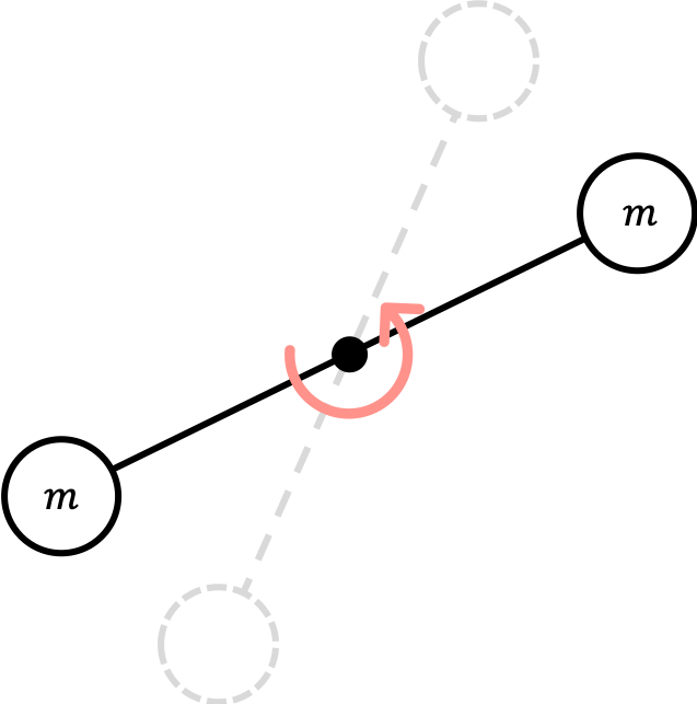
Using the definition of the moment of inertia above, we can calculate it as
\[I=\sum mr^2=m\left(\frac{\ell}{2}\right)^2+m\left(\frac{\ell}{2}\right)^2=\frac{m\ell^2}{2}\]If the center of rotation is on the edge of the baton, then the moment of inertia can be calculated as
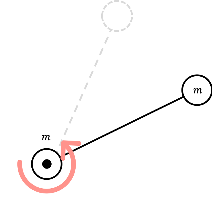
Again, applying the definition of the moment inertia again,
\[I=\sum mr^2=m(0)^2+m(\ell)^2=m\ell^2\]$I=\frac{m\ell^2}{2}$ if the center of rotation is at the center of the baton.
$I=m\ell^2$ if the center of rotation is at the edge of the baton.
Example 2: Rotating Uniform Rod
Now, let us assume that we have a uniform, homogenous rod with a total mass $M$ that is evenly distributed through the entirety of the length of the one-dimensional rod.
First, let’s assume that the center of rotation is at the center of the rod.
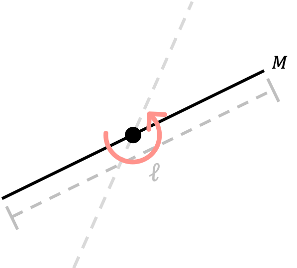
In this case, the moment of inertia can be calculated using the integral formula $I=\int dm r^2$. In order to calculate $I$ using this formula, we always need to start first by writing the mass in terms of the mass density and the spatial variable(s). In this case, the uniform mass density is $\rho=\frac{\text{total mass}}{\text{total length}}=\frac{M}{\ell}$. Therefore, we know that
\[dm=\frac{M}{\ell}dr\]Plugging this into the integral formula and integrating along the entirety of the length of the rod from $r=-\ell/2$ to $r=\ell/2$,
\[I=\int dm\text{ }r^2=\frac{M}{\ell}\int_{-\ell/2}^{\ell/2}dr r^2=\frac{M}{3\ell}\left(\frac{\ell^3}{8}-\frac{-\ell^3}{8}\right)=\frac{M}{3\ell}\frac{\ell^3}{4}=\frac{1}{12}M\ell^2\]If the center of rotation is instead on the edge of the rod, then our rotating rod instead looks like
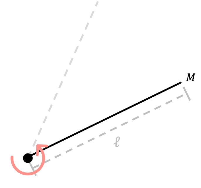
In this case, the moment of inertia can be calculated using a similar method, but this time integrating from $r=0$ to $r=\ell$ since our origin/center of rotation has been shifted. Using the fact that $dm=\frac{M}{\ell}dr$ is still true,
\[I=\int dm\text{ }r^2=\frac{M}{\ell}\int_{0}^{\ell}dr r^2=\frac{M}{3\ell}\left(\ell^3-0\right)=\frac{1}{3}M\ell^2\]$I=\frac{1}{12}M\ell^2$ if the center of rotation is at the center of the rod.
$I=\frac{1}{3}M\ell^2$ if the center of rotation is at the edge of the rod.
Example 3: Thin Cylindrical Shell
Consider a thin, hollow 2-D cylindrical shell rotating about its central axis.
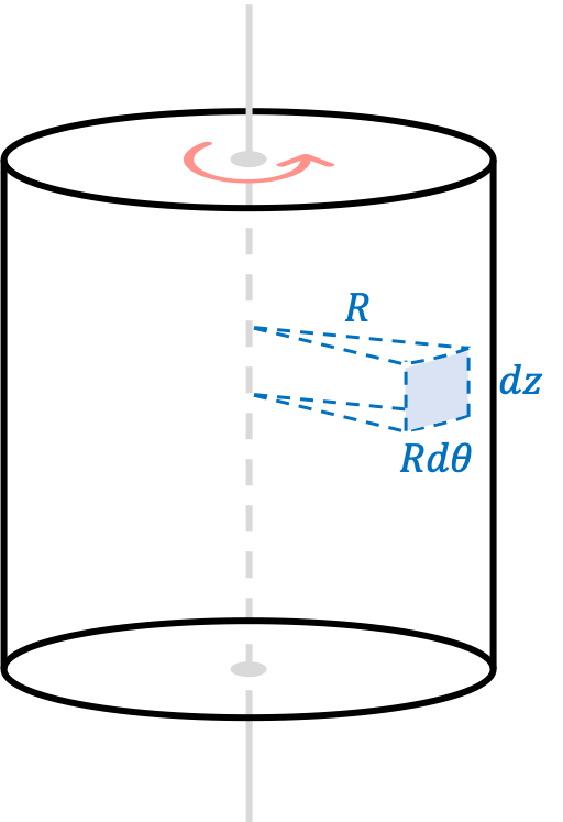
The area shaded in blue represents a small differential area element with total area $da=Rd\theta dz$, which can be derived using the differential spatial elements in cylindrical coordinates. The mass density of this shell is
\[\rho=\frac{\text{total mass}}{\text{total area}}=\frac{M}{2\pi R\ell}\]where $\ell$ is the height of the cylinder and $R$ is the radius of the cylinder. Using the same method to relate the differential mass and spatial elements, we have
\[dm=\rho da=\frac{M}{2\pi R\ell}Rd\theta dz=\frac{Md\theta dz}{2\pi \ell}\]Therefore, using the definition of the moment of inertia and integrating along the entirety of the circumference in the $\hat{\theta}$ direction and up the cylinder in the $\hat{z}$ direction,
\[I=\int dm\text{ }r^2=\frac{MR^2}{2\pi \ell}\int_0^\ell dz\int_0^{2\pi}d\theta=\frac{MR^2}{2\pi \ell}(\ell)(2\pi)\]Simplifying this expression gives us the moment of inertia of this rotating object.
$$I=MR^2$$
Example 4: Rotating Solid Sphere
Finally, let’s consider a solid, three-dimensional (meaning not hollow) sphere rotating on its central axis:

The small volume differential element of the sphere is given by $dV=rdrd\theta dz$, which can be derived using the differential spatial elements in cylindrical coordinates. The mass density of this shell is
\[\rho=\frac{\text{total mass}}{\text{total volume}}=\frac{M}{\frac{4}{3}\pi R^3}=\frac{3M}{4\pi R^3}\]where $R$ is the radius of the solid sphere. Using the same method to relate the differential mass and spatial elements as in the earlier example problems, we have
\[dm=\rho dV=\frac{3M}{4\pi R^3}rdr\text{ }d\theta\text{ }dz\]Using the definition of the moment of inertia and integrating along the entirety of the circumference in the $\hat{\theta}$ direction, along the radial direction in the $\hat{r}$ direction, and “up” the sphere in the $\hat{z}$ direction, we have that the total moment of inertia is by
\[I=\int dm\text{ }r^2=\frac{3M}{4\pi R^3}\int_0^{2\pi}d\theta\int_{-R}^{R}dz\int_0^{r_{\text{max}}}dr r^3\]Here, $r_{\text{max}}$ is the maximum distance from the central rotation axis, and is a function of $z$.
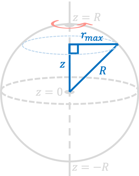
From this diagram and using the Pythagorean theorem, we can conclude that
\[z^2+r_{\text{max}}^2=R^2\longrightarrow r_{\text{max}}=\sqrt{R^2-z^2}\]Therefore, using this expression for $r_{\text{max}}$ as a function of $z$, our expression for the moment of inertia can be rewritten as
\[I=\frac{3M}{4\pi R^3}\int_0^{2\pi}d\theta\int_{-R}^{R}dz\left(\frac{1}{4}r_{\text{max}}^4\right)=\frac{3M}{16 R^3}\int_0^{2\pi}d\theta\int_{-R}^{R}dz(R^2-z^2)^2\]It can be shown using standard integration techniques (i.e. expanding the integrand using the binomial theorem and then using the power rule) that \(\int_{-R}^Rdz(R^2-z^2)^2=\frac{16R^5}{15}\). Therefore,
\[I=\frac{3M}{16 R^3}\int_0^{2\pi}d\theta\frac{16R^5}{15}=\frac{3M}{16 R^3}(2\pi)\frac{16R^5}{15}\]Simplifying the expression on the right hand side gives
$$I=\frac{2}{5}MR^2$$
Moments of Inertia of Other Common Geometries
Using similar processes as the ones shown in examples 3 and 4 above, the moments of inertia of other common geometric objects can be derived mathematically. For brevity, we will link the Wikipedia page to the results here. I don’t necessarily recommend you to memorize the moments, but it may help to keep this page handy.
Rotational Energy
Previously, we discussed that objects moving with some velocity $v$ inherently have a kinetic energy given by
\[U=\frac{1}{2}mv^2\]As you might expect, an object rotating about some axis with an angular speed $\omega$ also has an inherent energy, which we refer to as rotational energy. While rotational energy is not the same thing as kinetic energy, it turns out that we can derive an expression of it using the expression for kinetic energy. If we take the velocity $v$ as the tangential velocity of a rotating object, then we know from before that $v=r\omega$, where $\omega$ is the magnitude of the angular velocity, $v$ is the tangential speed, and $r$ is the distance of the object from the rotating center. Substituting this into the expression from above gives
\[U=\frac{1}{2}m(r\omega)^2=\frac{1}{2}(mr^2)\omega^2=\frac{1}{2}I\omega^2\]using the definition of the moment of inertia from above. Therefore, we can conclude that the rotational energy of a rotating object is given by
$$U=\frac{1}{2}I\omega^2$$
Example
The rotational energy of a rotating object is simply just another form of energy, and fits into our current working paradigm of different types of energies we have discussed. This means that it also contributes to and obeys the conservation of energy of objects. As an example, let’s consider the following problem:
A solid, three-dimensional ball of mass $m$ and radius $r$ starts from rest at a height $h$ and rolls down a slope, as shown in the figure below.
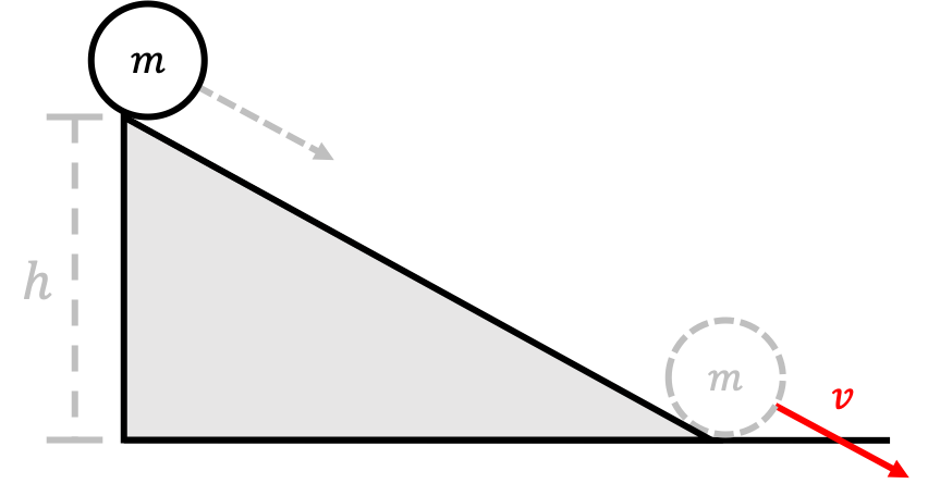
What is the linear speed $v$ of the ball when it leaves the incline? Assume that the ball rolls without slipping.
We can use conservation of energy to solve this problem. At the top of the inclined plane, the ball is not rotating or moving, and has gravitational potential energy $mgh$. At the bottom of the inclined plane, the ball has no gravitational potential energy, and but has both kinetic and rotational energy. Since there is no friction and total energy is conserved, we can conclude that
\[mgh=\frac{1}{2}mv^2+\frac{1}{2}I\omega^2\]From example 4 from above, we know that the moment of inertia of a solid, three-dimensional sphere is \(I=\frac{2}{5}mr^2\), so
\[mgh=\frac{1}{2}mv^2+\frac{1}{2}\frac{2}{5}mr^2\omega^2=\frac{1}{2}mv^2+\frac{1}{5}m(r\omega)^2\]Using the fact that the tangential speed $v=r\omega$,
\[mgh=\frac{1}{2}mv^2+\frac{1}{5}mv^2=\frac{7}{10}mv^2 \longrightarrow v^2=\frac{10}{7}gh\]Therefore, we can conclude that the velocity of the ball at the bottom of the inclined plane is
$$v=\sqrt{\frac{10}{7}gh}$$
Exercises
Problem 1
A disk, a hoop, and a solid sphere are released at the same time at the top of an inclined plane. They are all uniform and roll without slipping. In what order do they reach the bottom of the plane?
Problem 2
Consider a solid cylinder rolling about its axis.
- The moment of inertia of a solid cylinder about its axis is $I=\frac{1}{2}MR^2$, where $R$ is the radius of the cylinder and $M$ is the mass of the cylinder. If you were able to understand examples 3 and 4 from above and have experience with multivariable calculus and multi-dimensional integrals, show that the moment of inertia of this object is indeed $I=\frac{1}{2}MR^2$.
- If this cylinder rolls without slipping, what is the ratio of its rotational energy to its kinetic energy?
Problem 3
This problem is adapted from Caltech’s Ph1a course.
A mass $m$ is connected to a vertical revolving axle by two massless strings of length $L$, each making an angle of $45^{\circ}$ with the axle as shown.
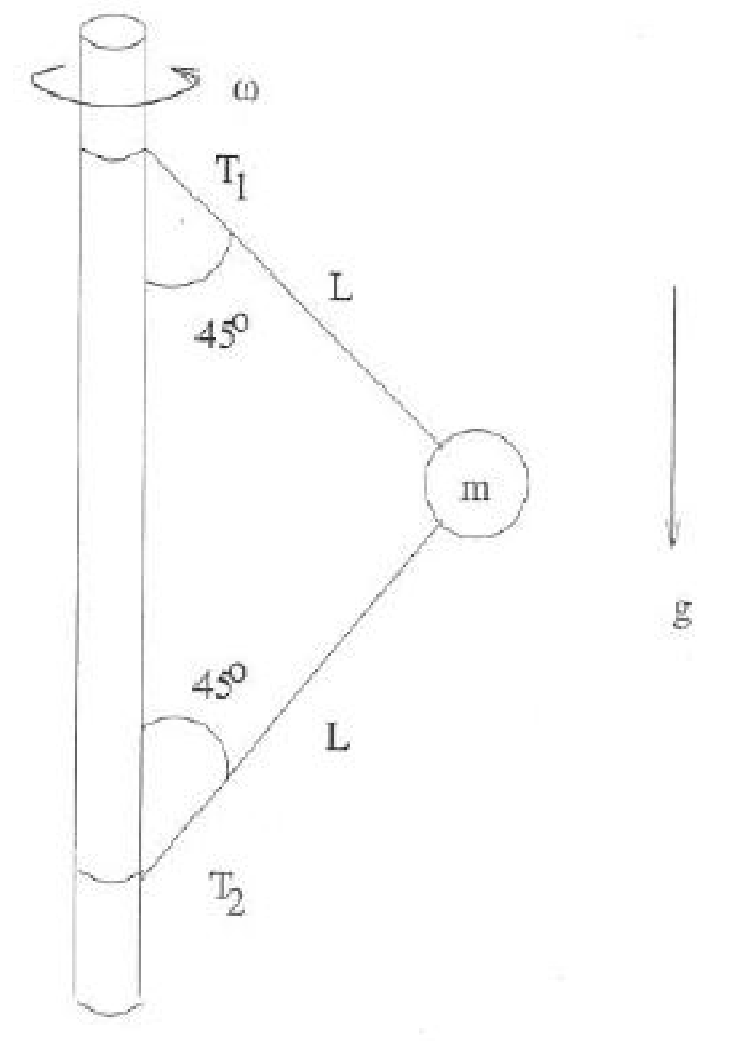
Both the axle and mass are revolving with large angular velocity $\omega$. You may neglect the radius of the axle.
- Draw a free body diagram for the forces acting on the mass $m$.
- Find the tensions $T_1$ and $T_2$ in the two strings. Give your answer in terms of $\omega, m, L, g$.
- What is the minimum angular velocity $\omega_{\text{min}}$ such that both strings remain taut? Give your answer in terms of $\omega, m, L, g$.