Newton’s Laws and Kinematic Equations: Rotational Motion
In this blast from the past, we’ll be looking at Newton’s laws once more, but this time in the frame of rotating objects.
Linear vs. Rotational Motion
Over the past couple of lessons, we’ve been interested in describing the motion of objects whose motion can be described as piecewise linear. This means that the objects are more or less moving in one direction for a particular interval in time, or the objects’ trajectories can be described nicely by breaking it down into the substituent vector components. Today, we’ll be introducing the mathematical formalism of describing rotational motion, which describes circular motion around a center point or axis.

At first pass, it might seem like these two types of motion should be described in very different ways. This is because in linear motion, we can have motion under constant velocity, but when studying rotational motion, everything is always accelerating because the direction of motion is always changing as object move around in a circle. However, as we will see, much of the formalism from Newton’s Laws can be re-adapted to describe rotational motion as well.
Defining Appropriate Quantities
The first thing we need to do is identify the variables and quantities that are of interest to us when talking about rotational motion. In studying linear motion, the most important concepts where the position $x$, the velocity $v$, and the acceleration $a$. In rotational motion, the instantaneous position, velocity, and acceleration of a rotating object is referred to as the tangential position, tangential velocity, and tangential acceleration, respectively. Each of these quantities has its own corresponding analog: angular position $\theta$, angular velocity $\omega$, and angular acceleration $a$.
| Linear Quantity | Tangential Position $$\vec{x}$$ |
Tangential Velocity $$\vec{v}$$ |
Tangential Acceleration $$\vec{a}$$ |
| Rotational Quantity | Angular Position $$\vec{\theta}$$ |
Angular Velocity $$\vec{\omega}$$ |
Angular Acceleration $$\vec{\alpha}$$ |
Our convention for defining angles will be the same as in polar coordinates: all angles will be defined relative to the $x$-axis:
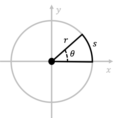
In this diagram, we have also introduced the variables $s$ and $r$. Here, $r$ represents the radius of rotation, while, $s$ represents the arclength distance on the circumference of the circle subtended by the angle $\theta$. To relate $s$, $r$, $\theta$, we can note that as $\theta$ increases, $s$ should increase by a proportionate amount. Therefore, we would expect a relationship between $s$ and $\theta$ that looks something like
\[s=k\theta+\theta_0\]for some constants $k, \theta_0$. We assume this linear relationship because of the hypothesized proportionate relationship between increases in $\theta$ and increases in $s$. We also know that when $\theta=2\pi$, $s=2\pi r$, the total circumference. Plugging this into the relationship above gives
\[2\pi r=k(2\pi)+\theta_0\longrightarrow k=r \text{ and } \theta_0=0\]This allows us to conclude that \(s=r\theta\). If we take the appropriate time the derivatives of this equation, it is not hard to see that $v=r\omega$ and $a=r\alpha$. This tells us that tangential quantities are related to their rotational analogs by a proportionality factor of $r$. To summarize,
$$s=r\theta, \quad v=r\omega, \quad a=r\alpha$$
We are also interested in the direction of the angular vectors. In order to talk about the direction of the angular displacement vector $\Delta \vec{\theta}$, we need to review polar coordinates. Recall that in a two-dimensional setting, we have two different ways of representing the coordinates of any point:
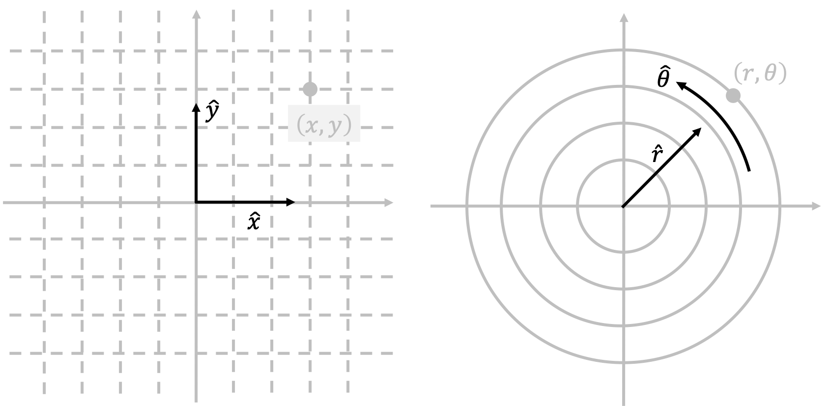
Cartesian coordinates and polar coordinates are two equally valid ways to represent points in two dimensions. Because we are dealing with circular trajectories in rotational motion, it is often more convenience to work in polar coordinates. In our case, because circular motion only involves motion along the $\hat{\theta}$ direction in the diagram above (since $r$ is a constant), this means that angular displacement vector $\Delta \vec{\theta}$ should be in the $\hat{\theta}$ (or $-\hat{\theta}$) direction.
For angular velocity $\vec{\omega}$ and angular acceleration $\vec{\alpha}$, the picture is a little more complicated. The direction of the angular velocity vector $\vec{\omega}$ can be found with the right-hand rule, which is a convenience tool that uses the chirality of your right hand in order to determine the correct direction of $\vec{\omega}$. The process of using the right-hand rule is simple:
- Grasp the axis of rotation with your right hand so that your fingers wrap in the direction of rotation.
- Your extended thumb then points in the direction of $\vec{\omega}$.
Using these rules, we can show that when an object rotates counterclockwise, the $\vec{\omega}$ vector points upwards, and when an object rotates clockwise, the $\vec{\omega}$ vector points downwards. There is an excellent figure that demonstrates this from Serway Physics, 9ed, shown below.
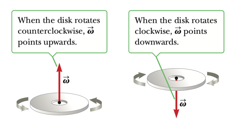
We typically denote the directions “upwards” and “downwards” as $+\hat{z}$ and $-\hat{z}$, respectively.
Finally, the directions of the angular acceleration $\vec{\alpha}$ and the angular velocity $\vec{\omega}$ are the same if the angular speed $\omega=\vert \vec{\omega}\vert$ is increasing with time, and are opposite each other if the angular speed $\omega$ is decreasing with time. All together, we have
| Angular Quantity | $$\Delta\vec{\theta}$$ |
$$\vec{\omega}$$ |
$$\vec{\alpha}$$ |
| Direction | Angular Position $$\pm\hat{\theta}$$ |
Angular Velocity $$\pm\hat{z}$$ |
Angular Acceleration $$\pm\hat{z}$$ |
Rotational Kinematic Equations
Using the relationship $s=r\theta$, we can derive a useful set of kinematic equations that describe the motion of rotation for any rotating object assuming that the angular acceleration $\alpha$ is some constant value.
As some object is rotating around in a circle, we can treat $s$ as some physical distance that should obey the kinematic equations that we derived previously for systems with constant acceleration. This means that, assuming the object isn’t speeding up or slowing down, we should have
\[s_f=s_i+v_it+\frac{1}{2}at^2\]We can divide this equation by the constant radius of rotation $r$ and use the fact that $\theta=\frac{s}{r}$ to find
\[\theta_f=\theta_i+\omega_it+\frac{1}{2}\alpha t^2\]This looks exactly as the linear kinematic equation, just with $\theta$’s substituted for $x$’s! Using this rather convenient result, we can also similarly prove that the rest of the kinematic equations also have their rotational analogs.
Assuming that angular acceleration $\alpha$ is constant...
- $\theta_f=\theta_i+\omega_it+\frac{1}{2}\alpha t^2$
- $\omega_f=\omega_i+\alpha t$
- $\theta_f=\theta_i+\frac{\omega_i+\omega_f}{2}t$
- $\omega_f^2=\omega_i^2+2\alpha(\theta_f-\theta_i)$
These are our kinematic equations for rotational motion! Note that, assuming that $\alpha$ is constant, every part of the rotating objects will always have the same angular speed $\omega$! This is in contrast to the tangential speed $v$, which scales as the radius $r$ away from the center increases. This means that, assuming constant angular speed $\omega$, an object rotating far away from the center of rotation will have a much faster tangential speed than an object rotating close to the center of rotation.
One caveat: while our results are correct, our method of proving them isn’t necessary rigorous. This is because we assumed that the arclength quantity $s$ obeyed the linear kinematic equations that assumed constant acceleration, but this is technically not the case. Because a rotating object is always changing direction, and therefore changing the direction of its velocity, a rotating object always has time-varying acceleration. This means that we cannot easily use the linear kinematic equations to describe the time dynamics of $s$. Luckily for us, so long as the speed of the rotating object is not changing, the math still works out to give the correct results in a fairly physically intuitive way, and an analytically sound proof is rather hard to explain.
Centripetal Acceleration
Let’s look at the the average acceleration for when a rotating object moves at constant speed during circular motion. As we have said above, although the speed of the object isn’t changing, the direction is, and so the object is still accelerating! Our goal is to find the magnitude and direction of this acceleration, which we call centripetal acceleration.
By definition of average acceleration, we know that
\[\vec{a}_{\text{avg}}=\frac{\vec{v}_f-\vec{v}_i}{t_f-t_i}\]where $\vec{v}_f$ is the final velocity and $\vec{v}_i$ is the initial velocity. Although the magnitude of the velocities $\vec{v}_f$ and $\vec{v}_i$ are the same, the directions are different, and so $\vec{v}_f-\vec{v}_i$ is still a nonzero vector. Let’s draw a diagram to help visualize that is $\vec{v}_f-\vec{v}_i$, where some object is traveling counterclockwise around a fixed point with trajectory radius $r$:
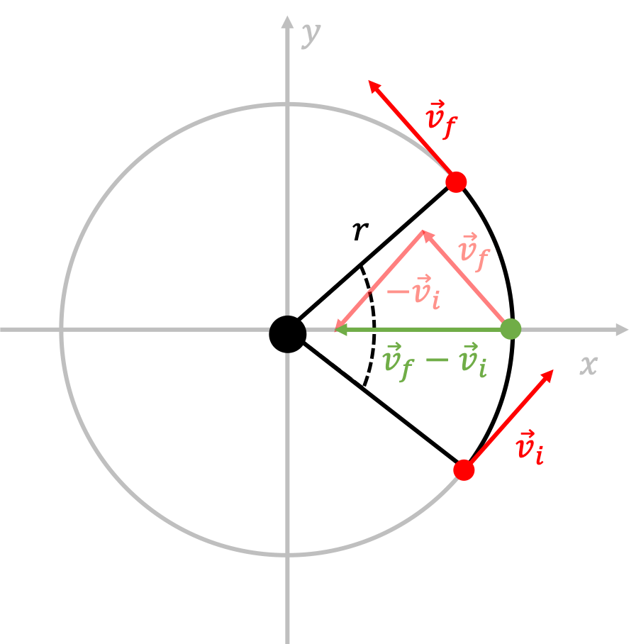
As we can see, in this particular case, the change in velocity \(\Delta \vec{v}=\vec{v}_f-\vec{v}_i\) from the average position along the trajectory from time $t_i$ to $t_f$ is pointing radially towards the center, as shown through the direction of the green vector $\Delta \vec{v}$. In this particular case, the average position in this time interval is on the $x$-axis, but it turns out that the average acceleration between any two time points $t_i$ and $t_f$ always points towards the center! You can draw a few additional diagrams like the one shown above to confirm that this is indeed always the case.
We also are interested in the magnitude of the centripetal acceleration $\vec{a}_{\text{avg}}$. To do this, let us take the angle $\Delta \theta$ subtended during the time interval $t_i$ to $t_f$ to be very small.
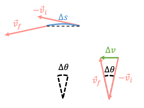
In this diagram, we have rotated the green-red triangle created by $\vec{v}_f, \vec{v}_i, \Delta \vec{v}$ by 90 degrees to clearly show that the two triangles in the diagram are similar triangles. We can relate the ratios of the side lengths of similar triangles in the following way:
\[\frac{x}{r}=\frac{\vert \Delta \vec{v}\vert}{v} \longrightarrow \vert \Delta \vec{v}\vert=v\frac{x}{r}\]where $v=\vert \vec{v}_f\vert = \vert\vec{v}_i\vert$. Now, when $\Delta \theta$ is fairly small, a good approximation that we can make is $x\approx \Delta s$, the arclength subtended by this angle $\Delta \theta$. As $\Delta\theta\rightarrow 0$, this approximation becomes exact. Therefore, we can conclude that to good approximation,
\[\vert \Delta \vec{v}\vert=v\frac{\Delta s}{r}=\frac{v}{r}\Delta s\longrightarrow \frac{\vert \Delta \vec{v}\vert}{\Delta t}=\frac{v}{r}\frac{\Delta s}{\Delta t}\]after dividing both sides of the equation by $\Delta t=t_f-t_i$. Using the definition of the magnitude of the tangential velocity $v=\Delta s/\Delta t$, and also the definition of centripetal acceleration $\vec{a}_{\text{avg}}=\Delta \vec{v}/\Delta t$, we can show
\[\vert \vec{a}_{\text{avg}}\vert = \frac{v}{r}\cdot v=\frac{v^2}{r}\]Therefore, we have shown that the centripetal acceleration of a rotating object is given by
$$\vec{a}_{\text{avg}}=\frac{v^2}{r}(-\hat{r})$$
The $(-\hat{r})$ vector is telling us that the centripetal acceleration is always pointing towards the center of rotation, as we showed above. Note that because $v=r\omega$, another way of writing the centripetal acceleration is \(\vec{a}_{\text{avg}}=-\omega^2\vec{r}\). Note that this formula for centripetal acceleration is only valid when the angular acceleration $\alpha=0$. In most cases, this will indeed be the case.
What is Centripetal Acceleration?
We have proven some interesting mathematical properties about centripetal acceleration, but what is it exactly physically? Perhaps the most important thing is that we can’t think about centripetal acceleration in terms of the picture we used for linear systems. That is, although the centripetal acceleration suggests that the rotating object is accelerating towards the center of rotation, therefore closing its distance between the object and the center of rotation, this is obviously not the case. The radius of rotation always remains a constant. However, this acceleration with nonzero magnitude is changing the direction of the velocity of the object without ever changing the magnitude of the velocity.
It is also important to emphasize that centripetal acceleration shouldn’t be thought of as a “new” force. We derived the mathematical properties of centripetal acceleration solely from thinking about the trajectory of the rotating object, not through considering the forces that source the centripetal acceleration. The forces that “cause” centripetal acceleration are often ones that you have seen before. For example, consider the mass $m$ attached to a string and a central nail on a frictionless table:
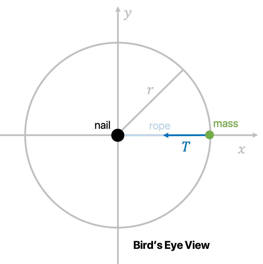
In this case, the rope provides a tension $\vec{T}$ that acts the force that gives us the centripetal acceleration necessary to keep the object moving at constant speed while its direction is constantly changing. In other cases, such as between the earth and the sun, the earth is kept in (roughly) circular orbit around the sun because of the gravitation force acting on the earth, which leads to a centripetal acceleration that keeps it in rotational motion. As we can see, centripetal acceleration is always the byproduct or consequence of a “centripetal force,” which is simply some force (i.e. tension or gravity or some other force) that causes centripetal acceleration.
Torque
We have introduced the rotational analogs for position, velocity, and acceleration. What about force? In linear systems, we know that forces are the things that cause linear acceleration. In rotating systems, there is something called torque that will be the thing that causes angular acceleration.
Let consider a scenario where we’re trying to do something simple: open (or in other words, rotate) a door. This is what it might look like from a bird’s eye view (picture taken from Serway Physics 9ed):
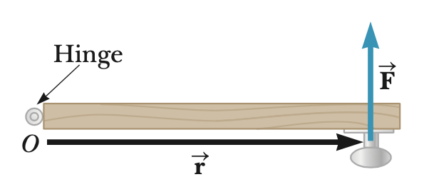
When we are opening the door, the things that dictate how fast the door “accelerates” open are
- how strong is the force that we push on the door?
- where do we push on the door?
Obviously, if we push on the door with the strength of Bruce Lee with large force, the door will rotate with a greater angular acceleration. Furthermore, we know from personal experience that it’s easier to push on a door when we push it far away from the hinge, rather than close to the hinge. In other words, we would expect the torque to be proportional to both the vectors $\vec{r}$, the displacement from the center of rotation, and $\vec{F}$, the force that we apply on the door. Indeed, this is the case: the torque $\vec{\tau}$ is defined by the vector relationship
$$\vec{\tau}=\vec{r}\times\vec{F}$$
As we can see, torque is a vector quantity and is denoted by $\vec{\tau}$, which is defined to be the cross product between $\vec{r}$ and $\vec{F}$. From this equation, we can see that the units of torque is $\text{N}\cdot\text{m}=\frac{\text{kg}\cdot\text{m}^2}{\text{sec}^2}=\text{J}$. If you’re familiar with what a cross product is, feel free to skip the next section.
Cross Products
In this section, we’ll introduce the idea of cross product just enough to motivate our understanding of torque. If you’re interested in a more thorough introduction, I suggest you visit this website.
The cross product is an operation that is similar to “multiplying” two vectors. It takes two vectors as input and spits out another vector. It is important to note that the cross product operation is only defined in three dimensional systems, not in two- or one- dimensional systems. The cross product of two vectors $\vec{a}$ and $\vec{b}$ is denoted as $\vec{a}\times\vec{b}$.
The magnitude of the cross product is given by the equation
\[\vert \vec{a}\times\vec{b}\vert = \vert \vec{a}\vert \vert \vec{b}\vert \sin\theta\]where $\theta$ is the angle between the two vectors. From this equation, we can tell that the magnitude of the cross product is maximized when $\vec{a}$ and $\vec{b}$ are perpendicular to one another, and is minimized (and zero) when $\vec{a}$ and $\vec{b}$ are parallel to one another.
The direction of the cross product is defined to be the direction perpendicular to both vectors $\vec{a}$ and $\vec{b}$, and is given by the right hand rule.
Finally, there are two important properties about the cross product:
- The cross product is anticommutative, meaning that $\vec{a}\times\vec{b}=-\vec{b}\times\vec{a}$.
- The cross product is distributive over addition, meaning that $\vec{a}\times(\vec{b}+\vec{c})=(\vec{a}\times\vec{b})+(\vec{a}\times\vec{b})$.
In 3D Cartesian coordinates, our unit vectors are $\hat{x},\hat{y}, \hat{z}$. These unit vectors are what we call cyclical in terms of calculating the cross products between them. This means that the cross product of a pair of them is equal to the remaining, other unit vector:
$$\hat{x}\times\hat{y}=\hat{z}, \quad \hat{y}\times\hat{z}=\hat{x}, \quad \hat{z}\times\hat{x}=\hat{y}$$
$$\hat{y}\times\hat{x}=-\hat{z}, \quad \hat{z}\times\hat{y}=-\hat{x}, \quad \hat{x}\times\hat{z}=-\hat{y}$$
and of course, because any vector is parallel with itself,
$$\hat{x}\times\hat{x}=0, \quad \hat{y}\times\hat{y}=0, \quad \hat{z}\times\hat{z}=0$$
Let’s go over a couple of common examples that you might find when taking cross products in the context of calculating torque:
Example 1: $\vec{r}=r\hat{x}$ and $\vec{F}=F\hat{y}$
By the definition of torque, $\vec{\tau}=\vec{r}\times\vec{F}=rF(\hat{x}\times\hat{y})=rF\hat{z}$.
Example 2: $\vec{r}=r\hat{y}$ and $\vec{F}=F\hat{x}$
By the definition of torque, $\vec{\tau}=\vec{r}\times\vec{F}=rF(\hat{y}\times\hat{x})=-rF\hat{z}$.
Example 3: $\vec{r}=r\hat{x}$ and $\vec{F}=F\hat{x}$
By the definition of torque, $\vec{\tau}=\vec{r}\times\vec{F}=rF(\hat{x}\times\hat{x})=0$.
Example 4: $\vec{r}=r_x\hat{x}+r_y\hat{y}$ and $\vec{F}=F_x\hat{x}+F_y\hat{y}$
By the definition of torque, $\vec{\tau}=(r_x\hat{x}+r_y\hat{y})\times(F_x\hat{x}+F_y\hat{y})$. Expanding, we have
$$\vec{\tau}=\vec{r}\times\vec{F}=r_xF_x(\hat{x}\times\hat{x})+r_xF_y(\hat{x}\times\hat{y})+r_yF_x(\hat{y}\times\hat{x})+r_yF_y(\hat{y}\times\hat{y})$$
Simplifying, we find that
$$\vec{\tau}=(r_xF_y-r_yF_x)\hat{z}$$
Newton’s Laws (for Rotating Systems)
Now that we have the basic framework of torque and angular quantities, we can also formulate a set of Newton’s Laws describe the classical motion of any object. They are:
- If the net torque on an object is zero, the object will remain at constant angular velocity. This means things that are at rest, stay at rest, and things that are rotating continue to move at constant angular velocity.
- The sum of all the torques on an object, $\sum \vec{\tau}$, is called the net torque $\vec{\tau}_{\text{net}}$, and is given by \(\sum \vec{\tau}=\vec{\tau}_{\text{net}}\propto\vec{\alpha}\), where $\vec{\alpha}$ is the angular acceleration. We will talk about what the proportionality constant exactly is later.
- For two objects $1$ and $2$ in contact, \(\vec{\tau}_{1\rightarrow 2}=-\vec{\tau}_{2\rightarrow 1}\).
Work and Energy
For rotating systems, the work $W$ due to a torque $\vec{\tau}$ is defined by
\[W=\int_{\vec{\theta}_i}^{\vec{\theta}_f}d\vec{\theta}\cdot\vec{\tau}(\vec{\theta}) \text{ or } W=\int_{\theta_i}^{\theta_f}d\theta\text{ }\tau(\theta)\]The first definition above is in 2- or 3- dimensions and is the more general case (we will talk about how to actually evaluate such an integral later). You will most likely find the second definition of work given more useful. Similarly, energy $U$ is defined by
\[-\frac{dU}{d\theta}=\tau(\theta)\]Exercises
Problem 1
A satellite of mass $m$ is said to be in geosynchronous orbit around the Earth of mass $M$ and radius $r_0$ if it always is above the exact same location on Earth all the time. In other words, the period $T$ of orbit of the satellite is 24 hours, which is the period of the rotation of the Earth.
Although we have not officially discussed this yet, the force of gravity $\vec{F}_g$ between two objects of mass $m_1$ and $m_2$ in space is given by
\[\vec{F}_g=\frac{Gm_1m_2}{r^2}\hat{r}\]where $G$ is called the gravitational constant, $r$ is the distance between the two objects, and $\hat{r}$ is the unit vector that points towards the direction of the other object.
Suppose that the satellite is a distance $r$ above the surface of the Earth.
- What is the angular velocity of the satellite?
- What is the tangential velocity of the satellite?
- What is the centripetal acceleration of the satellite?
- What is the angular acceleration of the satellite?
- Finally, the International Space Station is 408 km above the surface of the Earth. What tangential velocity does it need to achieve in order to be in geosynchronous orbit? Look up any constants, such as the gravitational constant or the mass and radius of the Earth, as necessary.
Problem 2
This problem is adapted from Serway Physics 9ed.
A $0.5$-kg ball that is tied to the end of a $1.5$-m light cord is revolved in a horizontal plane, with the cord making a $30^{\circ}$ angle with the vertical.
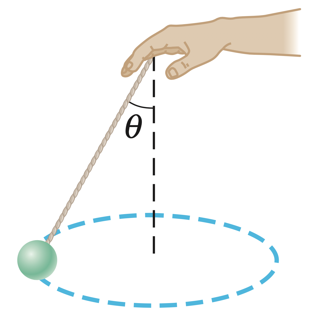
- Determine the ball’s speed.
- If, instead, the ball is revolved so that its speed is $4$ m/s, what angle does the cord make with the vertical?
- If the cord can withstand a maximum tension of $9.8$ N, what is the highest speed at which the ball can move?